Reducing Capital Costs
of Relief and Flare Systems
|
Our services help refineries, gas plants and LNG facility managers who need to conduct relief analysis for revamps or new designs, by greatly reducing relief systems capital expenditure and improving plant safety.
API Approved: Dynamic relief analysis has been recognized by API Standard 521 / ISO 23251 for more than 10 years as the gold standard for rigorous pressure relief calculation and is the officially recommended approach to reduce excessive over-sizing: “Conventional methods for calculating relief loads are generally conservative and can lead to overly sized relief- and flare-system designs. Dynamic simulation provides an alternative method to better define the relief load and improves the understanding of what happens during relief” - API Standard 521 / ISO 23251 - Section 5.22. Many Relief Systems are Oversized: We have over 20 years of experience in dynamic simulation based relief studies. We have helped clients improve plant safety, reduce the potential and magnitude of relief and flaring events, and saved hundreds of millions of dollars in revamp and greenfield capital costs. |
Our Services
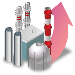
Revamp Relief AnalysisDynamic relief analysis is typically used for revamps to provide a rigorous analysis motivated by the need to ensure plant safety while eliminating unnecessary capital investments and lengthy shutdowns.
|
Greenfield Relief AnalysisGreenfield dynamic relief analysis is a new industry approach, prompted by capital cost efficiency. It is rooted in identifying and documenting conscious decisions to include over-design factors for future expansions, while using a methodology that eliminates excessively inflated capital costs.
|
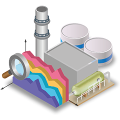
Flare System AnalysisAs an integral part of the relief system, flare system hydraulic analysis is an extremely important component in defining the system capacity and back-pressures for each upset scenario.
|
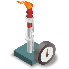
Why Dynamics?
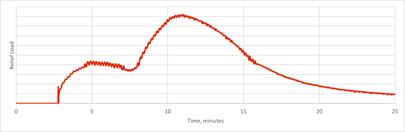
Upset scenarios that result in relief are transient in nature. The mass and energy flows in and out of the system change over time by accumulation or depletion. Actual relief events include 3 distinct stages. Each can only be adequately represented as a function of time. By rigorously predicting this transient behaviour, dynamic analysis provides the most accurate relief calculation. The three stages are:
Pressure BuildupThe pressure buildup stage is an accumulation of vapour in the system. Larger volumes take longer to pressure up than smaller ones. Additionally, it becomes harder to boil-off vapour as pressure increases.
This stage helps in offsetting the timing of relief between different systems in a site-wide upset, resulting in smaller flare headers, knock-out drums and flares. It also gives time for operator intervention, e.g. to shut-down a heat source. |
Relief PeakWhile the peak tells us the maximum capacity to size the relief valves for, it doesn’t tell us much more and hence really limits our design options.
For example a short spike is very different from a wide peak and the relief valves that handle it should be designed differently in terms of number of valves, orifice sizes and staging their set pressure. The ramp-up and peak are two integral components that help us eliminate typical relief valve issues like chattering. |
Decay or PlateauThis phase is the long term behaviour after the peak. We all want to design systems that decay fast and settle down to zero relief. Such systems are both safer and more economic.
Bottom Line: Dynamic relief analysis is a rare tool that greatly improves safety AND greatly reduces capital and operating costs. |
Good Safety Planning
|
Maintaining a safe plant requires the following critical components to be available at all times, and updated regularly:
|
Myths of Relief Analysis
Myth #1"Steady-state based calculations are always more conservative than dynamics and hence always safe to use"
This is a myth, as our survey indicates random set of results, some more conservative, and some less conservative than dynamics. This is because the assumptions used to make a steady-state calculation of a transient system are very subjective.
|
Myth #2"you can’t do dynamics unless you have all the details of your equipment, including geometry, performance curves, etc…"
This is a myth. While more information means better quality of results (i.e. lower calculated relief), reasonable conservative assumptions can be made using whatever records are available for a plant, supplemented by steady-state simulation models of current operation.
|
Myth #3"it is best to use steady-state based calculations for green-field facilities, and leave dynamics for revamps"
This is a myth too. A better approach is to use dynamics to get accurate relief loads, then use a healthy design multiplier to balance the risk of future revamp costs against investment.
|
Why Choose Us?
Excellent Execution and Delivery
Proven SuccessWe have a proven success record in delivering maximum value to our clients, resulting in significant capital savings and improved safety.
|
Dynamic SimulationWe use dynamic simulation for capturing the transient nature of relief scenarios, hence providing a highly accurate representation of potential relief and flaring events.
|
Agile ProjectsWe adopt a unique agile methodology for project management and delivery. Our studies are consistently delivered in shorter time frames than conventional studies.
|
Contact Us
To discuss your relief system and safety needs, feel free to contact us.
|
|
|
|